Translate

Sunday, 18 November 2012

BUS TOPOLOGY


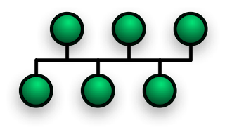
In local area networks where bus topology is used, each node is connected to a single cable. Each computer or server is connected to the single bus cable. A signal from the source travels in both directions to all machines connected on the bus cable until it finds the intended recipient. If the machine address does not match the intended address for the data, the machine ignores the data. Alternatively, if the data matches the machine address, the data is accepted. Since the bus topology consists of only one wire, it is rather inexpensive to implement when compared to other topologies. However, the low cost of implementing the technology is offset by the high cost of managing the network. Additionally, since only one cable is utilized, it can be the single point of failure. If the network cable is terminated on both ends and when without termination data transfer stop and when cable breaks, the entire network will be down.

Linear bus

The type of network topology in which all of the nodes of the network are connected to a common transmission medium which has exactly two endpoints (this is the 'bus', which is also commonly referred to as the backbone, or trunk) – all data that is transmitted between nodes in the network is transmitted over this common transmission medium and is able to be received by all nodes in the network simultaneously.
Note: The two endpoints of the common transmission medium are normally terminated with a device called a terminator that exhibits the characteristic impedance of the transmission medium and which dissipates or absorbs the energy that remains in the signal to prevent the signal from being reflected or propagated back onto the transmission medium in the opposite direction, which would cause interference with and degradation of the signals on the transmission medium.

Distributed bus

The type of network topology in which all of the nodes of the network are connected to a common transmission medium which has more than two endpoints that are created by adding branches to the main section of the transmission medium – the physical distributed bus topology functions in exactly the same fashion as the physical linear bus topology (i.e., all nodes share a common transmission medium).
Notes:
All of the endpoints of the common transmission medium are normally terminated using 50 ohm resistor.
The linear bus topology is sometimes considered to be a special case of the distributed bus topology – i.e., a distributed bus with no branching segments.

The physical distributed bus topology is sometimes incorrectly referred to as a physical tree topology – however, although the physical distributed bus topology resembles the physical tree topology, it differs from the physical tree topology in that there is no central node to which any other nodes are connected, since this hierarchical functionality is replaced by the common bus.
Monday, 5 November 2012

POINT TO POINT TOPOLOGY


The simplest topology is a permanent link between two endpoints. Switched point-to-point topologies are the basic model of conventional telephony. The value of a permanent point-to-point network is unimpeded communications between the two endpoints. The value of an on-demand point-to-point connection is proportional to the number of potential pairs of subscribers, and has been expressed as Metcalfe's Law.
Permanent (dedicated)
Easiest to understand, of the variations of point-to-point topology, is a point-to-point communications channel that appears, to the user, to be permanently associated with the two endpoints. A children's tin can telephone is one example of a physical dedicated channel.
Within many switched telecommunications systems, it is possible to establish a permanent circuit. One example might be a telephone in the lobby of a public building, which is programmed to ring only the number of a telephone dispatcher. "Nailing down" a switched connection saves the cost of running a physical circuit between the two points. The resources in such a connection can be released when no longer needed, for example, a television circuit from a parade route back to the studio.
Switched:
Using circuit-switching or packet-switching technologies, a point-to-point circuit can be set up dynamically, and dropped when no longer needed. This is the basic mode of conventional telephony

for aptitude exams click at this link

.http://aptitudeexam.blogspot.in/

Saturday, 3 November 2012

NETWORK TOPOLOGIES


Network topology is the arrangement of the various elements (links, nodes, etc.) of a computer or biological network.Essentially, it is the topological structure of a network, and may be depicted physically or logically. Physical topology refers to the placement of the network's various components, including device location and cable installation, while logical topology shows how data flows within a network, regardless of its physical design. Distances between nodes, physical interconnections, transmission rates, and/or signal types may differ between two networks, yet their topologies may be identical.
A good example is a local area network (LAN): Any given node in the LAN has one or more physical links to other devices in the network; graphically mapping these links results in a geometric shape that can be used to describe the physical topology of the network. Conversely, mapping the data flow between the components determines the logical topology of the network

TYPES OF TOPOLOGIES :-

Topology

There are two basic categories of network topologies:
Physical topologies
Logical topologies
The shape of the cabling layout used to link devices is called the physical topology of the network. This refers to the layout of cabling, the locations of nodes, and the interconnections between the nodes and the cabling.The physical topology of a network is determined by the capabilities of the network access devices and media, the level of control or fault tolerance desired, and the cost associated with cabling or telecommunications circuits.
The logical topology, in contrast, is the way that the signals act on the network media, or the way that the data passes through the network from one device to the next without regard to the physical interconnection of the devices. A network's logical topology is not necessarily the same as its physical topology. For example, the original twisted pair Ethernet using repeater hubs was a logical bus topology with a physical star topology layout. Token Ring is a logical ring topology, but is wired a physical star from the Media Access Unit.
The logical classification of network topologies generally follows the same classifications as those in the physical classifications of network topologies but describes the path that the data takes between nodes being used as opposed to the actual physical connections between nodes. The logical topologies are generally determined by network protocols as opposed to being determined by the physical layout of cables, wires, and network devices or by the flow of the electrical signals, although in many cases the paths that the electrical signals take between nodes may closely match the logical flow of data, hence the convention of using the terms logical topology and signal topology interchangeably.
Logical topologies are often closely associated with Media Access Control methods and protocols. Logical topologies are able to be dynamically reconfigured by special types of equipment such as routers and switches.

The study of network topology recognizes eight basic topologies:

  1. Point-to-point
 2. Bus
 3. Star
 4. Ring or circular
 5. Mesh
 6. Tree
 7. Hybrid
 8. Daisy chain

Friday, 2 November 2012

CCNA Networking : NETWORK

Example of LAN Network 


Example Of WAN Network


MAN Network Is Explained In Two Diagram


Networking : NETWORK

NETWORK

WHAT IS A NETWORK.....?

Network is the collection  of two or more then two computer connected to each other with help of the networking devices  like  routers, switches & hubs these all are further connected with the special type of networking wires  according to the pin configuration of each device.

TYPES OF NETWORK.

1. LAN NETWORK

2.WAN NETWORK

3. MAN NETWORK

1.) LAN NETWORK  :-   The full form of the LAN is Local Area Network . The local area network is established in small area or we can say LAN is implemented  locally .wi-fi is a example of LAN 
2.) WAN NETWORK :- The full form of WAN is the Wide Area Network . The wide area network
is the  network which is established huge area  or we can say that the  WAN  can be implemented in between countries or world wide . Internet is the example of the WAN
3.) MAN NETWORK :- The full form of MAN is the Metropolitan Area Network .A metropolitan area network (MAN) is a computer network that usually spans a city or a large campus. A MAN usually interconnects a number of local area networks (LANs) using a high-capacity backbone technology, such as fiber-optical links, and provides up-link services to wide area networks (or WAN) and the Internet.

INTRODUCTION


Network Elements
Choosing how and when to use the right network element is very crucial in designing a network. it is very important for you to spend extra time in studying this section

The network symbols for different networking elements
We will now discuss the different types of network elements in detail.

Network Interface Card (NIC) or a Network Adapter
The NIC is a hardware mounted onto a computer that can translate, send and received data across the network. It serves as the interface between the computer and the network medium.The NIC operates in the Layer 1 and 2 of the OSI Reference model. Although it is not a separate element by itself, the NIC is an essential element that makes computer networking possible. Without the NIC, there would be no networking.

PCI Ethernet cards, PCMCIA and USB devices
Each NIC has a unique 48-bit identifier burned into its chip. It is called a MAC (Media Access Control) Address. This identifier plays an important role in switching processes, which we will discuss in the next lessons to come.


Repeater
The simplest network element available is the repeater. It is made up of justone input port and one output port. It can only be used on Bus topologies.What the repeater does is only to amplify the same data signals it receives.

Thursday, 1 November 2012

what is networking .??

Networks consist of the computers, wiring, and other devices, such as hubs, switches and routers, that make up the network infrastructure. Some devices, such as network interface cards, serve as the computer�s connection to the network. Devices such as switches and routers provide traffic- control strategies for the network. All sorts of different technologies can actually be employed to move data from one place to another, including wires, radio waves, and even microwave technology. In other words to established a network between  different types of devices with the help of networking protocols is known as   NETWORKING  
In above diagram all networking devices are shown.......